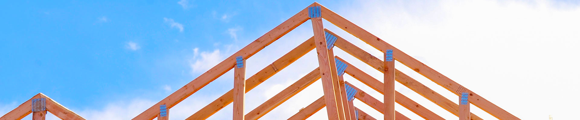
Trusses
A LEADING SUPPLIER OF TRUSSES IN FLORIDA
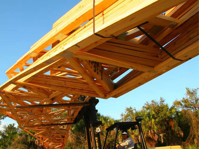
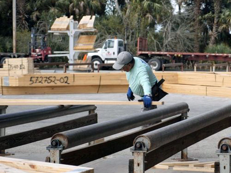
Raymond Building Supply operates three truss manufacturing locations in Florida, a 100,600 square foot facility in Auburndale, an 80,000 square foot facility in North Fort Myers and an 8.5 acre facility in Homestead, under the brand name of Deco Truss. With our network of state-of-art facilities located in Lee, Miami-Dade and Polk Counties, we are able to deliver finished product to customers in Southwest, Southeast and Central Florida.
Customers are able to submit and receive architectural drawings electronically for the design, engineering and production of trusses. The system guarantees each and every truss is manufactured to precise specification, reducing time and costs.Every truss is inspected and stamped by the craftsman, an example of the Quality Assurance Program that has made Raymond Building Supply one of the largest suppliers of trusses in Florida.
Questions? We’re Here to Help
If you have any questions about our company, products, or services, contact our team! We’re happy to help you find the information you’re looking for.